Main Overview
To apply the Hughes model to the surface mesh of the beehive, three steps are required:
- Define geometry and meshing
- Geometry definition
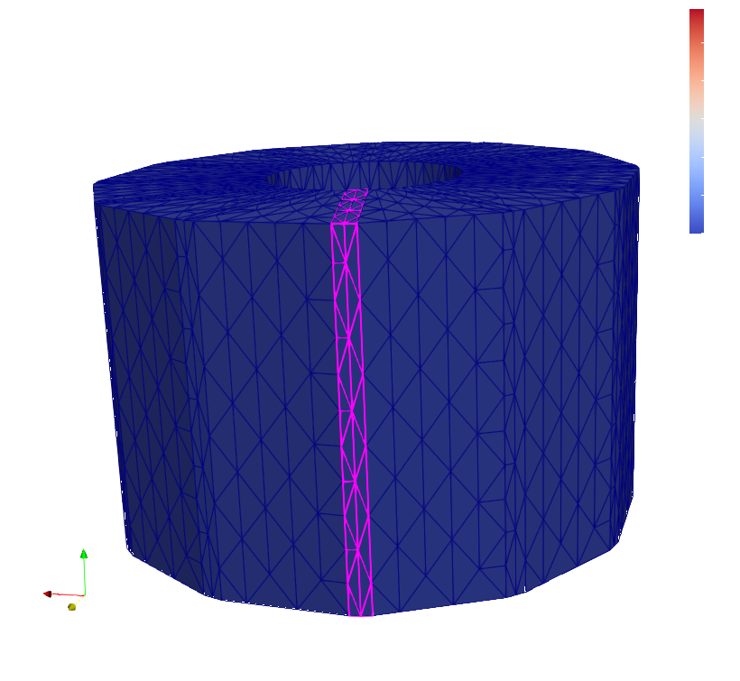
- Doors for exiting Bees
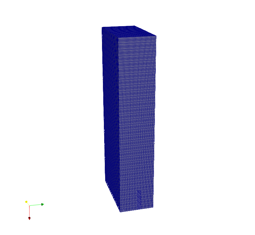
- Rectangular cube
- Converting an STL file to XDMF file
- Reading XDMF file in python

Geometry


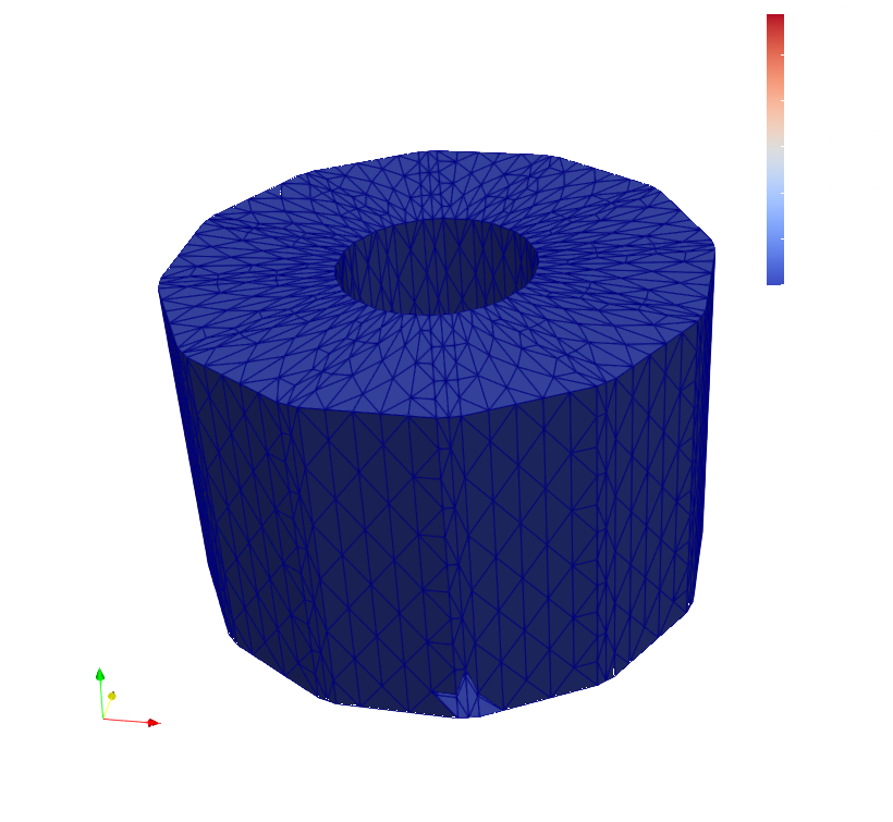
Considering the part of the region in which Bees are accumulated,
we design a rectangular cube using
Blender.
In the main region, when the rectangular cubes join the top part
of the region, we need to bisect a flux in two directions, which
is possible mathematically. But it's not easy to implement it in the context of DOLFIN . Hence, we
have to consider the small region of the main Beehive geometry.
Extending code
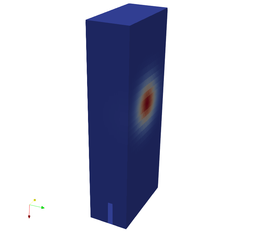
We aim to control the direction of exiting such that the spot goes to the top, then from the left side comes down and finally exits from the door. Therefore, we need to define the following terms for velocity term:
- right \( (z=1) \xrightarrow{\text{opposite of x-axis}} \) top(right): for this purpose, we use \( \color{purple}{ -e^{-(z-1)^2} }\) on x-direction
- top(right) \( \xrightarrow{\text{in the z-axis}} \) top(left): we use \( \color{blue}{e^{-(x+5)^2} }\) on z-direction regarding this geometry (since x = -5 on top of this geometry)
- top(left) \(\xrightarrow{\text{in the x-axis}} \text{left} (z = -1):\) we use \( \color{green}{e^{-(z+1)^2} }\) on x-direction regarding this geometry (since \( -1 \leq z \leq 1 \) ). It is important to note here that we need this term until \( x > 3.75 \) , and after that spot should go through the door.


